While searching for examples of roadbed cross sections, I thought these documents would be useful to modelers. While each includes interesting information, each represents a different era.
(Click on each drawing for a full size version. Zoom in on the full size drawing for more detail. )
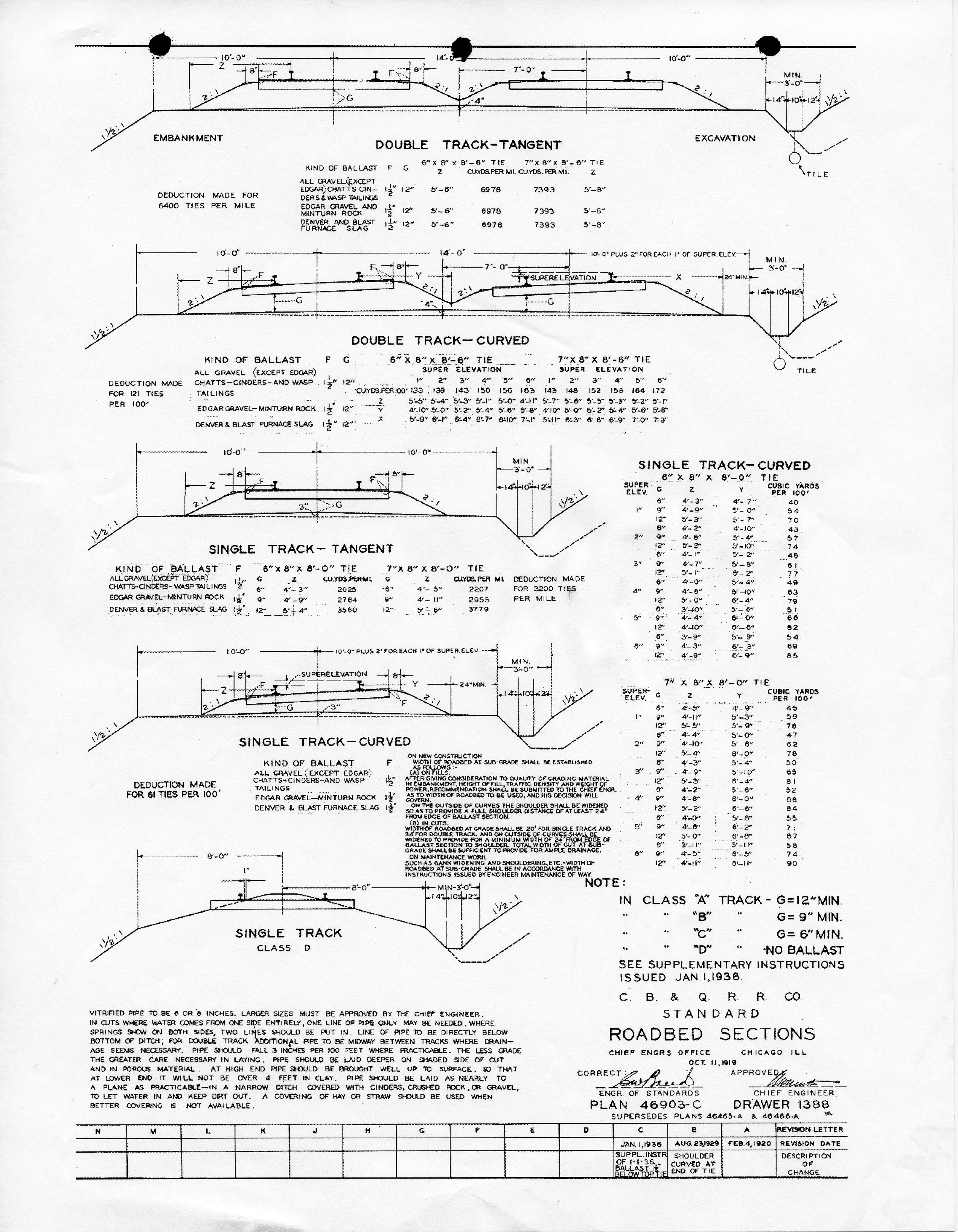
C. B. & Q. R. R. Co., last updated in 1936
This drawing last updated in 1936
includes roadbed sections for a variety of configurations. It's interesting to compare these specifications to those of the
UP document below.
I don't know where I found this drawing, so I'm unable to
acknowledge the source. If anyone recognizes it and
knows the source, please let me know.
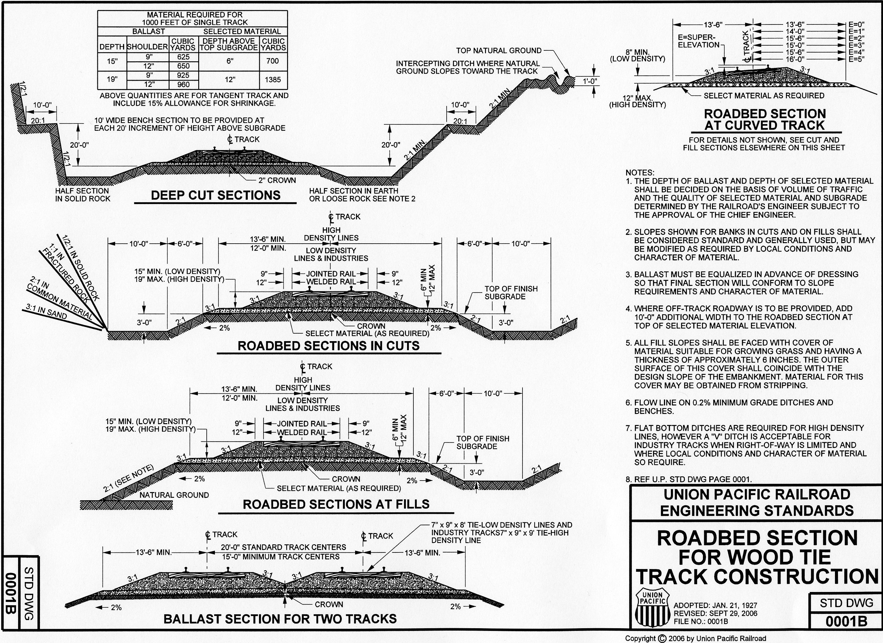
UNION PACIFIC, last updated in 2006
This drawing last updated in 2006 is from the Union Pacific's "Technical Specifications for Construction of Industrial Tracks". While the bulk of this document is focused on industrial track, this particular page provides information for modern high density as well as low density and industrial track. I find it interesting that the standard track spacing for high density track is now 20 feet (2-3/4" in HO) with a minimum of 15 feet (2" in HO). The size of the drainage ditches has also increased.
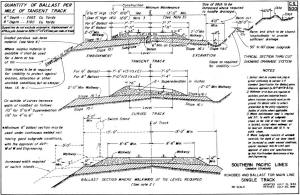
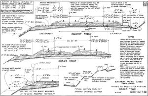
SOUTHERN PACIFIC, last updates 1984 and 1985
Bob Schrempp provided me
with copies of Southern Pacific's roadbed sections that were
last revised in 1984 and 1985.
I'm aware that the ballast and track at some locations of the
Union Pacific (ex. Southern Pacific) coast line below Salinas, CA rest on totally flat ground
without drainage ditches or any elevation above
grade.